
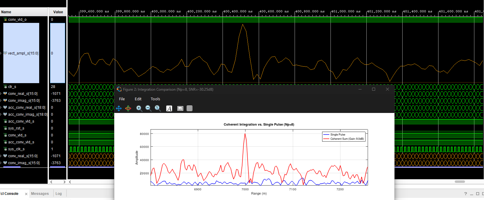
In Part 1, we established the theoretical foundations of our radar processing chain—covering complex I/O baseband modeling, LFM chirp generation, and a rigorous mathematical breakdown of pulse compression and coherent integration processing gains.
In this second and final installment, we transition directly from GNU Octave algorithmic models to high-performance VHDL implementation on an AMD/Xilinx Zynq-7000 (xc7z020clg400-1) FPGA, examining time-division folded FIRs, complex convolution, Standard FIFO latency tuning, and 250 MHz timing closure.
1. Quad-Channel Folded FIR Architecture
Implementing a 50-tap symmetric finite impulse response (FIR) filter across four parallel channels for complex cross-correlation ($II, IQ, QQ, QI$) can quickly exhaust available digital signal processing resources if instantiated directly.
To achieve high throughput while maintaining low resource utilization, the architecture employs 5x time-division folding (DSP_FOLD_STAGES_C = 5) leveraging the internal pre-adder and cascade features of the DSP48E1 primitive slice.
- Symmetric Folding: By exploiting filter symmetry, each 50-tap filter processes two symmetric data taps per clock cycle across folded stages.
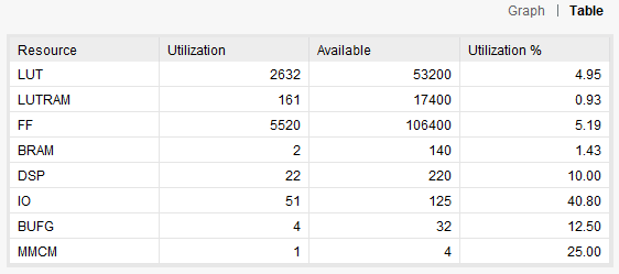
- Resource Efficiency: The entire quad-channel complex matched filter engine consumes only 20 DSP48E1 slices (10% utilization on the XC7Z020), leaving ample programmable fabric for downstream integration and control logic.
2. Complex Convolution & Convergent Rounding
The quad-channel architecture computes the full complex cross-product between the incoming digitized radar echo ($I_{\text{rx}} + jQ_{\text{rx}}$) and the reference chirp ($I_{\text{tx}} – jQ_{\text{tx}}$):
$$\text{Real Output} = \text{II} – \text{QQ} = (I_{\text{rx}}I_{\text{tx}} + Q_{\text{rx}}Q_{\text{tx}})$$
$$\text{Imaginary Output} = \text{IQ} + \text{QI} = (Q_{\text{rx}}I_{\text{tx}} – I_{\text{rx}}Q_{\text{tx}})$$
Bit-Growth & Convergent Rounding
Internal multiplication and summation within the DSP48E1 slices result in a 32-bit word width. To downsize the stream back to 16-bit word lengths (ADC_BIT_RES_C = 16) without introducing systematic DC offsets, the design implements convergent rounding (round-to-nearest-even arithmetic) via a custom conv_round function before truncating the lower bits.
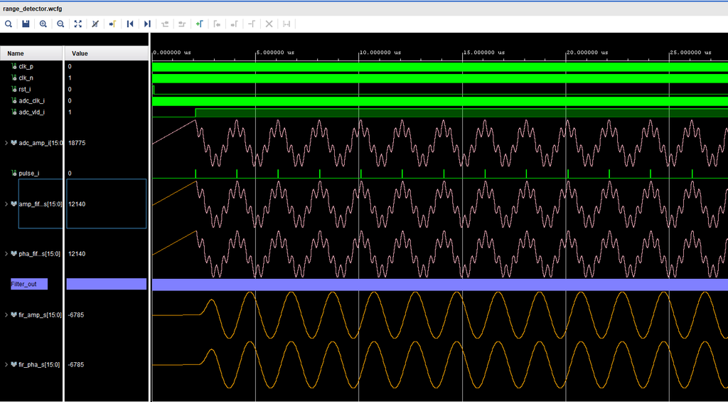
Figure 1: Simulation waveform displaying the complex I/O matched filter output streaming through the folded DSP architecture.
As demonstrated in the simulation waveform above, the raw noisy input pulses are successfully processed through the folded matched filter stages, eliminating background noise and yielding a clean, high-fidelity pulse compression response.
3. Standard FIFO Latency Tuning & Data Alignment
Managing clock-domain crossings (CDC) between the high-speed 250 MHz DSP clock domain and system interfaces requires careful FIFO selection.
Transitioning to a Standard FIFO
While First Word Fall Through (FWFT) FIFOs make data immediately available on dout, migrating to a Standard FIFO introduced a deterministic 1-clock-cycle read latency after asserting the read enable (rd_en).
Resolving the Pipeline Shift
- Initial Zero Padding: When switching to a Standard FIFO, the initial read cycle produced a leading zero in the convolution stream (
conv_ctr_s). - Internal Threshold Adjustment: Rather than adding external input registers that would disturb high-fanout control routing, we adjusted the internal validation threshold (
conv_ctr_vtrigger condition) insidecomplex_convolution.vhdto absorb the 1-cycle read latency natively. - Deterministic Peak Lock: This alignment eliminated leading-edge jitter and locked the final peak detection index precisely onto target bin 2333 ($R = 6999\text{ m}$), matching parity with our Octave golden reference model.
4. 250 MHz Timing Closure & Vivado Implementation
At 250 MHz, maintaining setup and hold timing across high-fanout control buses (cyc_ctr_s, clk_ena_i) across 20 distributed DSP slices presents a critical engineering challenge.
- Implementation Strategy: Configuring the Vivado project generation script (
range_detector.tcl) to enforce thePerformance_NetDelay_highimplementation strategy optimized place-and-route slack. - Timing Results: The final implementation achieved zero timing violations with a comfortable positive Worst Negative Slack (WNS) of ~0.158 ns at 250 MHz.
The complete design operates efficiently within tight programmable logic bounds:
5. CORDIC Vectoring & Final Peak Detection
Following 8-pulse coherent integration (which yields a theoretical 9.03 dB SNR boost), the Cartesian coordinate outputs ($I, Q$) are converted into polar magnitude and phase representations using a pipelined CORDIC IP core (IQ2Vector.xci).
The peak search engine (peak_search_proc) monitors the absolute magnitude stream, identifying the absolute maximum value and latching the corresponding range bin.
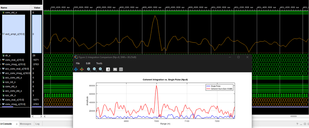
Figure 2: Final hardware peak detection output compared against the Octave simulation model.
As illustrated in the final simulation waveform above, the hardware output perfectly mirrors the theoretical peak profile generated in our initial Octave script.
Conclusion
By bridging rigorous mathematical modeling in Octave with cycle-accurate VHDL implementation, folded DSP48E1 arithmetic, and aggressive Vivado timing closure, we have successfully deployed a production-grade radar signal processing chain on Zynq-7000 silicon.
All VHDL source files, testbenches, IP configuration scripts (range_detector.tcl), and simulation assets are fully verified and available in the GitHub Repository.
Leave a Reply